

2026 Best Analog Splitter 4 20mA for Global Buyers?
Choosing the 2026 best Analog Splitter 4 20ma requires more than comparing prices or terminal counts. Global buyers need stable isolation, accurate signal duplication, and predictable performance inside noisy control cabinets. A splitter may receive one 4–20 mA transmitter signal and deliver two or more independent outputs. That simple function supports PLCs, DCS platforms, alarm systems, historians, and remote displays.
MarketsandMarkets’ Industrial Automation Market research projects continued expansion through 2027, driven by connected factories, process modernization, and stronger measurement requirements. Grand View Research also identifies process instrumentation as a growing technology segment across oil and gas, water treatment, chemicals, energy, and manufacturing. These reports do not prove that every application needs a splitter. They do show why dependable signal conditioning remains commercially important.
Steve Mackay, an industrial instrumentation author and control-systems specialist, describes the loop as “the most common analog signal used in industrial process control.” That practical view still matters in 2026. Buyers should examine loop burden, isolation voltage, output accuracy, response time, power supply range, calibration drift, and hazardous-area approvals. Check the datasheet carefully. Marketing language can hide limits.
Real installations expose the difference. A splitter mounted beside a variable-frequency drive may face electromagnetic noise and temperature changes. A compact DIN-rail unit may save space but provide fewer diagnostic features. There is no universal winner. This guide compares leading Analog Splitter 4 20ma products by measurable performance, documentation quality, lifecycle support, and field suitability. Some rankings remain debatable, especially where manufacturers publish incomplete long-term reliability data. That uncertainty deserves attention.
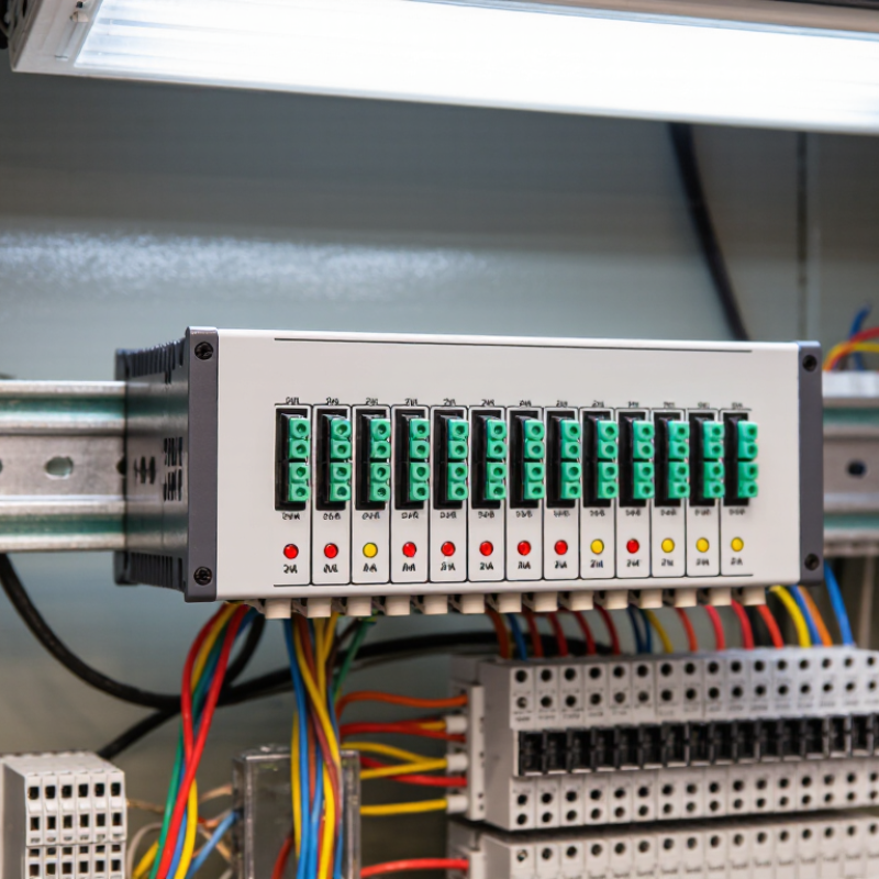
What a 4–20 mA Analog Splitter Is and How It Works
A 4–20 mA analog splitter is an industrial signal device that duplicates one analog current signal. It accepts a single current-loop input and produces two separate outputs. The input usually represents a measured value, such as pressure, temperature, or flow. Four milliamps indicates the lower measurement limit. Twenty milliamps indicates the upper limit. This live-zero design helps distinguish a valid low reading from a broken wire. No software is required.
Inside the splitter, an input circuit measures loop current and converts it into a stable internal signal. Signal conditioning removes unwanted electrical noise. The device then creates two matching output currents for separate controllers, displays, or recording systems. Each output can often feed a different load. Galvanic isolation reduces ground-loop interference between connected equipment. Some models need an external power supply. Others draw operating power from the loop. Read the wiring diagram carefully.
For global purchasing, confirm the input range, output type, supply voltage, and isolation method. Check whether outputs are active or passive. Verify the maximum load resistance. Accuracy, response time, temperature range, and enclosure rating also matter.
Regional electrical requirements should match the installation site. In a control cabinet, leave space for wiring and heat movement. During commissioning, inject 4, 12, and 20 mA, then compare both outputs. A practical test may reveal more than a polished specification sheet. Do not assume every splitter handles long cables equally. Grounding mistakes remain common, even in well-designed systems. Specification reviews deserve a second look.
Key Specifications for Comparing 4–20 mA Signal Splitters
When comparing a 4–20 mA signal splitter, start with the signal path, not the housing. A practical unit accepts one transmitter loop and provides two independent outputs. Check whether each output supports 4–20 mA, voltage, or both. Galvanic isolation matters when controllers use different power domains. It reduces ground-loop errors and protects downstream input cards. In field work, a non-isolated device may seem cheaper, then create unstable readings near motor drives. That lesson is easy to miss.
Accuracy should be reviewed with specific conditions. Look for maximum error, temperature drift, and repeatability across the operating range. A specification of ±0.1% may apply only at 24 VDC, 25°C, and a stated load. Those details matter. Confirm the allowable load resistance for every output, since long cables can exceed it. Response time also affects fast pressure or flow changes. A slow output can hide a short process upset. Check loop-powered versus externally powered operation, because wiring and maintenance differ.
For global installations, inspect terminal spacing, enclosure rating, ambient temperature, and installation documentation. Verify whether the splitter fits a 24 VDC control cabinet and withstands vibration, humidity, and electrical noise. A technician should test zero, span, and output tracking before commissioning. Record readings at 4, 12, and 20 mA. Do not rely only on a brochure. Some comparisons ignore calibration access and diagnostic indicators. That omission can increase service time. I would question impressive accuracy claims without test methods, sample size, or long-term drift data.
2026 Best Analog Splitter 4–20 mA for Global Buyers? – Key Specifications for Comparing 4–20 mA Signal Splitters
| Comparison Criterion | Passive, Non-Isolated | Active, Non-Isolated | Active, Galvanically Isolated | Dual-Output Isolated |
|---|---|---|---|---|
| Primary application | Simple signal duplication where ground loops are not a concern | Signal duplication with a reliable auxiliary power supply | Industrial control, hazardous potential differences, and noise reduction | One transmitter signal feeding two electrically independent control systems |
| Input signal | 4–20 mA, typically 2-wire loop-powered | 4–20 mA, usually active or passive input compatible | 4–20 mA, commonly configurable for active or passive input | 4–20 mA, commonly configurable for active or passive input |
| Output configuration | Usually 1 or 2 passive current outputs | Typically 1 or 2 active 4–20 mA outputs | Typically 1 or 2 isolated 4–20 mA outputs | Two independent isolated 4–20 mA outputs |
| Auxiliary power | Not normally required | Typically 18–30 V DC | Typically 18–30 V DC; some versions accept a wider DC range | Typically 18–30 V DC |
| Electrical isolation | None | None | Input-to-output and often output-to-power isolation | Input-to-output and output-to-output isolation |
| Typical accuracy at 20 °C | Approximately ±0.2% to ±0.5% of span | Approximately ±0.1% to ±0.2% of span | Approximately ±0.1% to ±0.2% of span | Approximately ±0.1% to ±0.2% of span |
| Temperature drift | Often up to ±0.02% of span/°C | Commonly ±0.01% to ±0.02% of span/°C | Commonly ±0.01% to ±0.02% of span/°C | Commonly ±0.01% to ±0.02% of span/°C |
| Maximum load resistance | Often limited to approximately 250–500 Ω per output, depending on loop voltage | Commonly 500–750 Ω per output at 24 V DC | Commonly 500–750 Ω per output at 24 V DC | Commonly 500–750 Ω per output at 24 V DC |
| Response time | Usually below 30 ms | Usually below 20 ms | Usually below 20 ms; verify the specified rise time | Usually below 20 ms; verify the specified rise time |
| HART communication | May attenuate or block HART unless specifically designed for transparency | Requires a HART-compatible version and suitable loop impedance | Requires explicit HART pass-through support | Requires explicit HART pass-through support on each applicable channel |
| Typical isolation rating | Not applicable | Not applicable | Commonly 1.5–3.0 kV AC test voltage; confirm the datasheet rating | Commonly 1.5–3.0 kV AC test voltage; confirm channel-to-channel rating |
| Installation format | Compact module or DIN-rail module | DIN-rail or panel-mounted module | DIN-rail module, commonly 6–22.5 mm wide | DIN-rail module, commonly 17.5–35 mm wide |
| Operating temperature | Commonly −20 to +60 °C | Commonly −20 to +60 °C | Commonly −20 to +60 °C or −40 to +70 °C | Commonly −20 to +60 °C or −40 to +70 °C |
| Best selection advantage | Lowest power consumption and simplest wiring | Good accuracy with straightforward installation | Strong protection against ground loops and common-mode interference | Independent outputs for PLC, DCS, recorder, or safety systems |
| Main limitation | Consumes loop voltage and generally provides no isolation | Needs auxiliary power and does not eliminate ground-loop problems | Higher cost and power consumption than non-isolated designs | Wider module and higher cost; verify output load sharing and isolation details |
Input, Output, Isolation, and Compatibility Requirements
2026 Best Analog Splitter 4 20mA for Global Buyers?
A reliable 4–20 mA analog splitter starts with the input type. Confirm whether the transmitter provides an active or passive loop. Check the input burden, allowable loop voltage, and signal accuracy. A splitter may accept one signal and provide two isolated outputs, but only if its supply can support the total load. Output selection also matters. Choose active outputs for powered control systems, or passive outputs for receiving devices with their own loop supply. Verify output range, maximum load resistance, and temperature drift under real operating conditions.
Isolation protects sensitive equipment from ground loops, surges, and different cabinet potentials. Specify input-to-output and output-to-output isolation separately. Reinforced isolation may be useful near motors or long field cables. Compatibility is broader than connector size. Review terminal wiring, supply voltage, response time, installation method, and communication transparency. Some systems carry digital data over the current loop. A splitter that distorts that signal can create confusing maintenance faults. I have seen installations pass bench tests but fail after cable lengths changed.
Tips: Test the splitter with the actual transmitter and receiver. Measure loop voltage at the farthest terminal. Keep a small margin below the rated load. Confirm regional certification and documentation before shipment. Do not rely on a perfect datasheet; wiring assumptions are often incomplete. When specifications conflict, record the uncertainty and request a practical test sample. Small details matter.
How to Evaluate Splitter Accuracy, Reliability, and Safety
2026 Best Analog Splitter 4-20mA for Global Buyers?
Evaluating a 4-20mA analog splitter starts with accuracy, not marketing language. Check total error across temperature, load resistance, and supply voltage. A device rated at 0.1% may perform differently in a hot control cabinet. Look for input-to-output isolation, low drift, and a fast response time. These details matter when a pressure signal controls a valve or alarm.
Reliability depends on real installation conditions. Confirm the splitter supports the required loop power and output burden. Check terminal strength, enclosure protection, and resistance to vibration. During commissioning, technicians should test 4mA, 12mA, and 20mA points on every channel. Record readings after warm-up. Small deviations can reveal wiring problems or poor grounding.
Safety needs practical verification. Review isolation ratings, overvoltage protection, EMC test information, and regional compliance documents. Requirements may differ between industrial sites and process areas. Do not assume a certificate covers every installation. Ask for test reports, wiring diagrams, and clear failure behavior. If power fails, outputs should move to a predictable state or provide a detectable fault. No splitter is perfect. Even a well-designed unit can drift after years of heat exposure. That uncomfortable possibility deserves a maintenance interval, spare capacity, and a documented calibration check.
Selecting the Best 4–20 mA Analog Splitter for Global Applications
Choosing a 4–20 mA analog splitter requires more than checking its channel count. Start with the signal range, output load, isolation level, and supply voltage. Confirm whether one input must serve two independent control systems.
Galvanic isolation is valuable when sensors, controllers, and power supplies use different grounds. It can reduce ground-loop errors and protect sensitive instruments. In field installations, enclosure temperature matters too. A splitter rated for laboratory conditions may drift inside a hot cabinet.
Check accuracy, linearity, response time, and long-term stability. Small errors can affect dosing, pressure control, or flow monitoring.
I have seen installations fail because engineers overlooked output burden resistance. The device worked on the bench, but not after long cable runs. That assumption was costly.
Review wiring diagrams, terminal spacing, polarity, and diagnostic indicators before purchasing. For global applications, request clear technical documents, test reports, and regional compliance information.
A reliable supplier should explain calibration methods and provide traceable performance data. Still, published specifications may not reflect every installation. Verify them with a practical site test.
Tips:
Select a splitter with isolated outputs when control systems have separate grounds. Leave voltage headroom for cable resistance. Test at 4, 12, and 20 mA. Record readings at normal and extreme temperatures. Avoid choosing only by price. A slightly higher initial cost may reduce troubleshooting time. Also, plan for maintenance access. This detail is easy to miss.
