

How to Choose a High Torque Brushless DC Motor?
Choosing a High Torque Brushless Dc Motor is not simply a matter of picking the largest torque rating on a product page. A motor that looks powerful on paper can stall, overheat, or waste energy when paired with the wrong load. The phrase “high torque” needs context: torque at what speed, for how long, and under what cooling conditions? Rated torque describes continuous operation; peak torque may be available only briefly. That distinction matters. A compact motor may deliver strong starting force, while a larger unit may handle sustained work with less thermal stress. More torque is not always better.
Before selecting a High Torque Brushless Dc Motor, define the load, required speed, acceleration, duty cycle, and available voltage. Consider the machine it will drive: a conveyor carrying uneven boxes has different demands from a wheel that starts and stops repeatedly. Check the torque-speed curve, continuous and peak ratings, winding temperature limits, shaft dimensions, and mounting pattern. A gearbox can increase output torque, but it also changes speed, efficiency, and backlash. One number rarely tells the whole story.
When specifications seem close, compare thermal behavior, efficiency, controller compatibility, and expected operating conditions. Verify claims against manufacturer datasheets, then test the motor with the real load where practical. Bench results can differ inside a warm enclosure or with a misaligned coupling. It is easy to focus on torque and overlook noise, vibration, or maintenance access. A careful choice balances performance, operating life, and cost—not just an impressive headline figure.
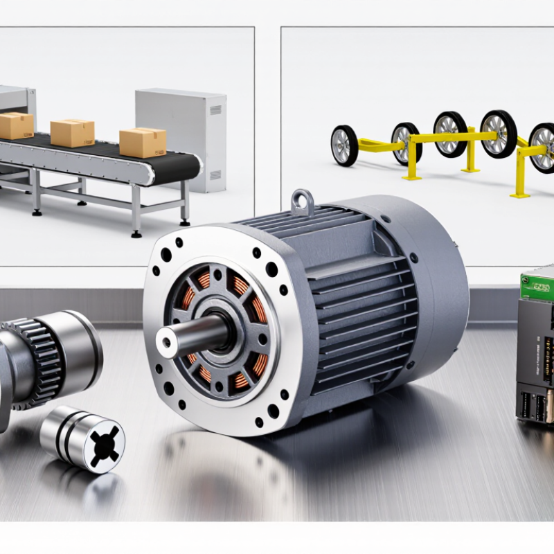
Define the Application and Operating Requirements
Before choosing a high-torque brushless DC motor, describe the actual job, not just the peak torque on a datasheet. Record continuous and peak torque, shaft speed, acceleration time, load inertia, and how often the motor starts, stops, or reverses. A conveyor moving heavy bins needs different sizing from a compact actuator that delivers brief bursts of force. Note the supply voltage, available controller current, ambient temperature, and space for cooling, too. Small details matter.
Operating time is easy to underestimate. The International Energy Agency’s 2011 report, Energy-Efficiency Policy Opportunities for Electric Motor-Driven Systems, estimates these systems use about 45% of global electricity. That figure is broad, not a motor-sizing rule. Still, it highlights why duty cycle and efficiency deserve attention. A motor that handles a short peak may overheat during repeated cycles. Check the manufacturer’s torque-speed curves and thermal limits against the full operating profile, then allow for real-world variation. I would revisit the assumptions after testing; calculated loads are not always the loads seen on the shop floor.
Tips: Measure the load at the shaft if possible. Include the weight of attached parts, friction, and the time spent at each speed. Keep a simple cycle log. Peak torque alone can mislead.
How to Choose a High Torque Brushless DC Motor? - Define the Application and Operating Requirements
| Application | Torque Requirement | Typical Speed Range | Operating Profile | Supply and Control | Key Requirements to Define |
|---|---|---|---|---|---|
| Conveyor drive | Approximately 2–10 N·m at the motor shaft; more may be required at the conveyor roller after gearing. | About 300–1,500 rpm at the motor; roller speed depends on the reduction ratio and roller diameter. | Often continuous or long-duration operation, with extra torque needed during startup and when the belt is loaded. | Select a DC bus compatible with the system; define speed regulation, reversing, and braking needs. | Belt load, roller diameter, acceleration time, starts per hour, ambient temperature, and allowable speed variation. |
| Mobile robot or AGV traction | A planning range of 20–100 N·m at a geared wheel output may be appropriate for some units; calculate from vehicle mass, wheel radius, grade, and acceleration. | Typically low wheel speed, with motor speed determined by the gear ratio and required travel speed. | Intermittent travel with frequent starts, stops, turns, and short acceleration peaks. | Battery voltage range, regenerative braking behavior, encoder feedback, and traction-control interface. | Vehicle mass, wheel size, maximum grade, desired acceleration, duty cycle, tire grip, and peak current limit. |
| Pump drive | Approximately 0.5–5 N·m at the motor shaft for some small pump duties; actual torque depends on pump type, pressure, flow, and speed. | Often about 1,000–3,000 rpm, subject to the pump’s specified operating range. | May be continuous; startup torque and operation against pressure can affect motor sizing. | Define DC supply, speed-control method, overload response, and whether closed-loop speed regulation is needed. | Pump type, required flow and pressure, fluid temperature, viscosity, inlet conditions, and permissible noise. |
| Linear actuator or positioning axis | Approximately 10–80 N·m at a geared output is a possible planning range; screw lead, transmission efficiency, and load determine the required value. | Usually low output speed; motor speed is set by the gearbox and the required linear travel rate. | Intermittent motion with acceleration and holding periods; a brake may be needed for loads that can back-drive the mechanism. | Define position feedback, limit switches, holding strategy, and controller current limits. | Load, stroke, screw lead, required travel time, accuracy, backlash, holding duration, and mounting orientation. |
| Mixer or agitator | Approximately 5–30 N·m at the motor shaft may suit some small systems; viscous or changing loads can require substantially more torque. | Often about 100–1,000 rpm, depending on the mixing process and any reduction gearing. | May run continuously or in batches; startup with material in the vessel can create a demanding load. | Specify adjustable speed, overload handling, and enclosure protection appropriate to the installation. | Material viscosity, batch size, impeller geometry, startup condition, cleaning method, and required speed range. |
Sizing note: The ranges above are illustrative starting points, not universal motor specifications. Confirm the load’s continuous and peak torque, speed, acceleration, duty cycle, and thermal conditions. Compare torque at the same shaft location: a gearbox can increase output torque while reducing speed, with losses that depend on the gearbox.