

Quality Mold

What Is a Screw Conveyor and How Does It Work?

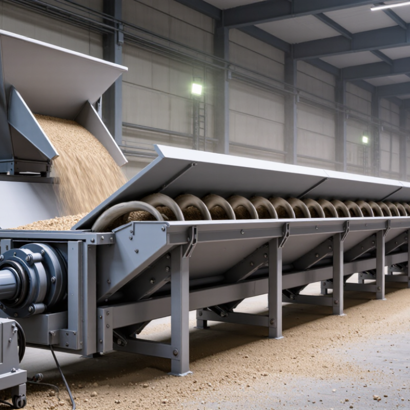
A Screw Conveyor is a practical machine for moving powders, granules, and small bulk materials through controlled, enclosed paths. Inside its trough or tube, a rotating helical flight pushes material forward, much like a large metal auger. The system can transport material horizontally, incline it gently, or feed it into mixers, hoppers, and packaging lines. Its compact footprint makes it valuable where space is limited.

Industry demand reflects the wider growth of automated material handling. Grand View Research’s Conveyor System Market Size, Share & Trends Analysis Report, 2023–2030, projects continued market expansion, supported by manufacturing, food processing, mining, and logistics. MHI’s 2024 Industry Report also highlights automation and data-driven equipment as major investment priorities. These reports do not describe every Screw Conveyor application, but they show the operational pressure behind reliable bulk handling.

The operating principle is simple. The motor turns the screw, the flight creates forward movement, and the housing controls dust and spillage. Practical performance depends on pitch, diameter, speed, fill level, material moisture, and incline angle. CEMA’s Screw Conveyors for Bulk Materials remains a key engineering reference for capacity calculations, component selection, and safety considerations. Still, real plants are less tidy. A design can look correct on paper and bridge material during a humid shift. Poorly selected speed may also generate heat, wear, or inconsistent feeding. Understanding these limitations helps engineers choose the right configuration instead of treating every Screw Conveyor as a universal solution.
What Is a Screw Conveyor and How Does It Work?

Screw Conveyor Definition: Helical Flights Inside a Trough or Tube

A screw conveyor is a mechanical device that moves bulk material through a controlled path. Its defining feature is a rotating shaft fitted with helical flights. These flights form a continuous spiral surface inside a trough or tube. As the shaft turns, each flight pushes material forward along the conveyor’s length. The trough usually remains open for easy loading and inspection. A tube provides better containment for dusty, fine, or weather-sensitive materials.

During operation, the motor supplies rotation through a drive assembly. Material enters through an inlet and rests on the lower section of the trough. The rotating flights create forward movement, although some sliding and rolling always occur. Flight pitch, diameter, speed, and inclination affect capacity. A conveyor installed at an angle may carry less material than a horizontal unit. That detail is often underestimated.

In practical maintenance work, uneven wear commonly appears near the inlet. Abrasive material can thin the flights, while sticky material may build up between the spiral and casing. Operators should inspect bearings, seals, shaft alignment, and emergency stops at planned intervals. The flight edge should not touch the trough. It should not. Even slight contact can increase noise, power demand, and damage. Material properties also matter. Moisture, temperature, bulk density, and particle size should guide the design. A conveyor that performs well with dry granules may struggle with wet powder, despite having similar capacity calculations.

Main Components: Flights, Shafts, Troughs, Bearings, and Drive Systems

What Is a Screw Conveyor and How Does It Work?

A screw conveyor moves bulk material through a rotating helical flight inside a trough. The flight is the working surface. Its pitch, diameter, and rotation speed control capacity, residence time, and material movement. A shaft supports the flight and transfers torque from the drive system. In heavy-duty designs, a larger shaft reduces deflection, but it can also increase power demand.

The trough contains the material and controls its path. U-shaped troughs support inspection and cleaning, while enclosed designs help limit dust release. Bearings support the shaft at the inlet, outlet, and sometimes intermediate points. Their position matters. A poorly aligned hanger bearing can create friction, heat, and uneven wear. The drive system normally combines a motor, gearbox, coupling, and guards. OSHA conveyor guidance stresses guarding around moving parts, while CEMA’s Screw Conveyors for Bulk Materials provides established methods for capacity and power calculations.

Industry demand also explains the equipment’s popularity. Grand View Research valued the global conveyor systems market at approximately 10.68 billion dollars in 2023 and projected continued growth through 2030. That figure covers several conveyor types, not screw conveyors alone. This distinction matters. Actual performance depends on bulk density, moisture, abrasiveness, loading rate, and incline. A design that works for dry grain may struggle with sticky sludge. Field testing should challenge the calculation, not merely confirm it. The neat formula is sometimes wrong. Regular bearing checks and flight inspection remain practical safeguards.

Operating Principle: Axial Material Flow at Approximately 15–150 rpm

A screw conveyor moves bulk solids through a trough or tube with a rotating helical flight. Its operating principle is simple: axial material flow, driven by friction, gravity, and the screw’s forward push. At approximately 15–150 rpm, the shaft turns slowly enough to control handling, yet fast enough for steady transfer. That range is not universal.

In practical installations, lower speeds suit fragile, abrasive, or densely loaded materials. Higher speeds can increase capacity, but they may cause particle degradation, dust, or irregular discharge. As the flight rotates, material should advance along the conveyor rather than spin in place. That sounds obvious. A full trough, incorrect pitch, or poor inlet design can disturb this axial movement. Operators often check motor load, bearing temperature, and discharge consistency during commissioning. These observations reveal problems before costly downtime occurs.

Choosing speed requires more than a catalog calculation. Material moisture, particle size, temperature, incline, and fill level all influence performance. For example, a damp powder may cling to the flight at one speed, then surge at another. Small changes matter. Field experience shows that measured flow rarely matches the first estimate perfectly. Engineers should record actual throughput and adjust speed gradually, while protecting guards and following site safety procedures. The design may look correct on paper, but field behavior deserves another question.

Design Factors: Capacity, Power, Diameter, Speed, and Inclines up to 45°

What Is a Screw Conveyor and How Does It Work?

A screw conveyor moves bulk material through a rotating helical flight inside a trough or tube. Its performance depends on capacity, power, diameter, speed, and incline. The Conveyor Equipment Manufacturers Association’s Screw Conveyor Engineering Guide calculates capacity from screw diameter, pitch, rotational speed, and fill level. A larger diameter usually carries more material. However, oversizing can increase cost and reduce control.

Power selection requires more than motor torque. CEMA guidance considers material density, friction, conveyor length, speed, and elevation. Abrasive or sticky materials need additional allowance. For example, a heavy mineral load demands more power than dry grain at the same capacity. Speed also matters. Excessive speed may cause degradation, dust, or poor loading. Lower speeds often protect fragile products, but they reduce hourly output.

Tips: Check actual bulk density before final sizing. Confirm the loading percentage with measured feed conditions. CEMA incline factors commonly show capacity falling to about 40% of horizontal performance at 45 degrees. That figure varies with material and flight design. Inclines also increase power demand and may cause rollback. I have seen designs fail because engineers used catalog capacity without checking moisture. That shortcut looks efficient, but it is not reliable. Use CEMA calculations, field testing, and independent mechanical review before commissioning.

Industrial Applications: Conveying Bulk Solids Across Distances up to 45 m

A screw conveyor moves bulk solids through a trough or enclosed tube with a rotating helical flight. As the screw turns, its flights push material forward along the conveyor axis. A motor and gearbox provide torque, while bearings support the rotating shaft. The system can transport powders, granules, pellets, and damp mixtures. It works steadily. Feed rate depends on screw speed, pitch, fill level, and material behavior. A controlled inlet prevents surging and uneven loading. At the outlet, gates or chutes direct material into storage, processing, or packaging equipment.

In industrial plants, screw conveyors commonly move bulk solids across distances up to 45 m. They connect silos to mixers, hoppers to bagging lines, and crushers to screening units. Enclosed designs help limit dust, weather exposure, and product loss. This matters in cement, minerals, chemicals, food ingredients, biomass, and wastewater treatment. However, 45 m is not an automatic design limit. Long runs increase power demand, shaft deflection, wear, and maintenance access concerns. Engineers should check bulk density, moisture, temperature, abrasiveness, and required capacity before selecting dimensions. Small changes in moisture can cause sticking or blockage. Field tests may show good performance in dry conditions, yet seasonal humidity can expose weaknesses. That gap deserves honest testing. Inspection doors, bearing protection, and emergency stops support safer operation. A practical layout leaves room for cleaning and component replacement, not just installation.