

What Are the Top Types of Capacitor Bank?
Choosing the right Capacitor Bank begins with understanding the electrical problem, not selecting the cheapest enclosure. In factories, substations, and renewable-energy sites, capacitor banks support voltage stability, improve power factor, and reduce avoidable reactive-current flow. Their performance depends on load patterns, harmonics, switching frequency, temperature, and available fault current.
Power-quality engineer Roger C. Dugan offers a practical warning: “Power-factor correction must be evaluated as part of the whole power system.” That principle remains important. A fixed capacitor bank may suit a steady motor load. An automatic, switched bank works better when production demand changes throughout the day. Detuned banks and harmonic-filter banks require closer attention when variable-speed drives or converters are present. Pole-mounted and metal-enclosed designs serve different installation environments.
Small details matter. A poorly selected bank can create resonance, nuisance tripping, or shortened capacitor life. It may even worsen distortion instead of correcting it. That outcome is easy to underestimate.
This guide examines the top types of Capacitor Bank and the conditions that influence each choice. It considers installation location, control methods, protection devices, ventilation, discharge resistors, and maintenance access. IEEE 18 and IEC 60871 provide useful technical reference points, but site measurements remain essential. A nameplate cannot reveal every system interaction.
The classification is not perfect. Some banks combine several functions, and manufacturers use overlapping terms. That can confuse buyers. Careful engineers therefore compare operating data, harmonic studies, switching requirements, and lifecycle costs before approving a design.
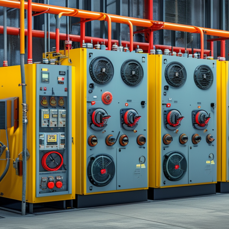
Fixed Capacitor Banks: Standard kVAr Ratings for Constant Loads
What Are the Top Types of Capacitor Bank?
Fixed Capacitor Banks: Standard kVAr Ratings for Constant Loads
Fixed capacitor banks provide steady reactive power compensation for loads that operate with little variation. Typical applications include continuously running motors, transformers, pumps, and ventilation systems. Common ratings include 5, 10, 15, 25, 50, 75, 100, and 150 kVAr. Larger installations may require 200 kVAr or more.
The correct rating depends on measured demand, not guesswork. For example, a motor drawing excessive reactive power during long production shifts may suit a 25 kVAr bank. A larger workshop with several constant motors could need 100 kVAr. A qualified engineer should review voltage, load current, power factor, and operating schedules before selection. Small errors matter.
Installation also requires suitable fuses, switching equipment, discharge resistors, and ventilation. Capacitors should remain accessible for inspection and thermal checks. Harmonic-producing equipment can create resonance, even when the load appears constant. In that case, a plain fixed bank may perform poorly, and a detuned design may be safer. A neat rating table can mislead. Real measurements are better. Periodic power-quality testing confirms whether the bank improves power factor without causing overheating, nuisance trips, or excessive voltage rise. One overlooked detail is future expansion; a bank sized tightly today may become unsuitable after another motor is installed.
What Are the Top Types of Capacitor Bank? - Fixed Capacitor Banks: Standard kVAr Ratings for Constant Loads
| Typical Fixed Bank Rating | Common 3-Phase System Voltage | Approx. Line Current at 400 V | Typical Constant-Load Application | Recommended Installation Context | Typical Control Arrangement |
|---|---|---|---|---|---|
| 5 kVAr | 380–415 V | 7.2 A | Small induction motors, compact pumps, and lightly loaded transformers | Installed close to a continuously operating inductive load | Direct connection with suitable switching and discharge protection |
| 10 kVAr | 380–415 V | 14.4 A | Small machine tools, fans, compressors, and workshop motors | Suitable where the reactive demand remains relatively stable | Fixed connection or dedicated contactor switching |
| 15 kVAr | 380–415 V | 21.7 A | Medium-sized motors and ventilation equipment | Mounted at the motor control panel or local distribution board | Fixed connection with capacitor-duty switching equipment |
| 25 kVAr | 380–415 V | 36.1 A | Production-line motors, pumps, and air-handling systems | Used for a steady inductive load operating for extended periods | Local fixed bank with fuses or circuit-breaker protection |
| 30 kVAr | 380–415 V | 43.3 A | Medium industrial motors and refrigeration compressors | Installed where the corrected load can be isolated during shutdown | Contactor-switched fixed bank or feeder-mounted bank |
| 50 kVAr | 380–415 V | 72.2 A | Larger pumps, compressors, conveyors, and processing equipment | Suitable for dedicated feeders with a consistent operating profile | Fixed bank with short-circuit, overload, and discharge protection |
| 75 kVAr | 380–415 V | 108.3 A | Large motors, industrial fans, and continuously loaded plant equipment | Installed at a main distribution section serving a stable load group | Single fixed bank or several permanently connected sections |
| 100 kVAr | 380–415 V | 144.3 A | Large motor groups, chilled-water pumps, and manufacturing feeders | Requires adequate busbar capacity, ventilation, and isolation clearance | Fixed bank with capacitor-duty contactor or breaker switching |
| 150 kVAr | 380–415 V | 216.5 A | Heavy industrial process loads and large motor control centers | Used when reactive demand is high and does not vary substantially | Dedicated feeder with coordinated protection and discharge resistors |
| 200 kVAr | 380–415 V | 288.7 A | Large plant sections, high-capacity pumps, and fixed process machinery | Installed in a main low-voltage switchboard or dedicated capacitor cubicle | Fixed multi-section bank with common isolation and protection |
| 300 kVAr | 380–415 V | 433.0 A | Large industrial feeders and continuously operating high-power equipment | Requires engineered busbars, thermal management, and fault coordination | Fixed multi-section arrangement with individually protected sections |
Current values are approximate for a balanced three-phase system and are calculated using I = Q ÷ (√3 × V) at 400 V. Actual capacitor-bank ratings depend on the system voltage, frequency, permitted voltage tolerance, harmonic environment, and the required power-factor correction level. Fixed banks are best suited to loads with a stable and predictable reactive-power demand.
Automatic Switched Banks: APFC Control for 0.95–0.99 Power Factor
What Are the Top Types of Capacitor Bank?
Automatic Switched Banks: APFC Control for 0.95–0.99 Power Factor
Automatic switched capacitor banks use APFC controllers to match reactive compensation with changing electrical demand. The controller reads voltage and current through measuring transformers, then connects or disconnects capacitor steps. This response helps maintain a power factor between 0.95 and 0.99 without leaving excessive capacitive energy during light loads.
A practical system may use several steps, such as 10, 20, and 25 kvar. Smaller steps improve accuracy, while larger steps reduce switching frequency. The target setting should reflect the utility requirement, motor profile, and operating schedule. A fixed target of 0.99 is not always ideal. It can encourage overcorrection when large motors stop suddenly.
Harmonics require careful attention. Capacitors can amplify resonant currents near dominant harmonic frequencies, especially in facilities with drives, rectifiers, or welding equipment. Detuned reactors can reduce this risk, but their rating must match the capacitor bank and network conditions. During commissioning, measure current distortion, temperature, and switching behavior under real loads. A clean calculation may still fail on a noisy bus. That happens.
Maintenance staff should inspect contactors, fuses, ventilation paths, and discharge resistors. Dust, heat, and frequent switching shorten component life. APFC control also needs sensible time delays, because rapid switching may create unnecessary stress. Field settings are sometimes treated as permanent, yet production loads change. Review them after major equipment upgrades.
Automatic Switched Capacitor Banks: APFC Control for 0.95–0.99 Power Factor
This calculated operating example shows how an automatic power factor controller switches capacitor steps as inductive load changes. The target operating range is maintained between 0.95 and 0.99 to reduce reactive power demand without excessive correction.
Example basis: a 400 V three-phase system with a 100 kW active load profile. Capacitor steps are selected according to the estimated reactive power requirement; actual results depend on load characteristics, harmonics, switching resolution, and controller settings.
Detuned Capacitor Banks: 5.67–7% Reactors for Harmonic Protection
Detuned capacitor banks are a practical choice when power-factor correction meets variable-speed drives, rectifiers, or data-center loads. A 5.67–7% series reactor shifts the bank’s resonant point below the fifth harmonic. At 50 Hz, tuning occurs near 210–189 Hz. The exact point changes with system frequency and capacitor tolerance.
This separation reduces harmonic amplification and limits excessive capacitor current. It does not remove harmonics. IEEE 519-2022 sets a 5% voltage THD limit for systems rated up to 1 kV, with a 3% limit for individual harmonics. Engineers should verify these values at the point of common coupling, not only inside the switchboard. IEC 60831-1 and IEC 60831-2 also define important performance and safety requirements for low-voltage shunt capacitors.
Field measurements matter. A 480 V panel may show acceptable voltage THD at light load, then rise sharply when several drives accelerate together. Installers should record current THD, capacitor temperature, reactor noise, and switching frequency. A 7% reactor offers stronger detuning, but it also creates greater voltage drop and heating. That trade-off is often underestimated. The U.S. Department of Energy reports that motor-driven systems consume about 70% of industrial electricity, making harmonic-aware correction increasingly relevant. Yet a standard setting is never a substitute for a site study.
High-Voltage Capacitor Banks: IEC 60871 Designs Above 1 kV
High-voltage capacitor banks above 1 kV are mainly designed for reactive-power compensation, voltage support, and harmonic control. IEC 60871 covers AC shunt capacitors used in these systems. Common arrangements include fixed banks, switched banks, and tuned filter banks. Fixed banks suit stable loads. Switched banks respond to changing demand. Filter banks combine capacitance with reactors, reducing selected harmonic currents.
Grid demand is becoming less predictable. The IEA Electricity 2024 report forecasts global electricity demand growth of about 4% annually from 2024 to 2026. That expansion increases the need for efficient voltage management, especially near industrial plants and renewable-energy connections. Engineers must check insulation levels, inrush current, switching transients, temperature rise, and discharge performance. Small errors can create expensive failures.
Field experience shows that nameplate voltage alone is not enough. A bank may pass routine calculations yet perform poorly under harmonic distortion. IEC 60871 testing helps verify capacitance, dielectric losses, thermal behavior, and overvoltage endurance. Protection may use current imbalance relays, fuses, or unbalance detection, depending on the bank structure. The practical weakness is often coordination. Reactor tuning, relay settings, and network impedance must be reviewed together. Otherwise, a well-built bank can amplify resonance instead of controlling it. That risk deserves more attention. (Sources: IEC 60871 series; IEA, Electricity 2024.)
Harmonic-Filter Banks: IEEE 519 Limits and 5% THD at ≤1 kV
Harmonic-filter banks combine capacitors, reactors, and sometimes damping resistors. They correct low power factor while reducing harmonic currents from drives, rectifiers, and power supplies. At systems rated up to 1 kV, IEEE 519 commonly allows 5% total voltage distortion at the point of common coupling. Individual voltage harmonics generally should remain below 3%. These figures describe voltage quality, not every current condition.
That distinction matters. IEEE 519 current limits depend on the short-circuit ratio at the connection point and the facility’s load current. A bank can show 5% voltage THD internally, yet fail the applicable current TDD limit at the utility interface. Engineers should measure both voltage and current with a calibrated power-quality analyzer. Record readings during light load, normal production, and peak demand. Real equipment reveals what simulations miss.
Tuning is critical. A filter designed near the fifth harmonic may amplify another frequency if system impedance changes. Detuned banks offer safer general correction, but they may provide less harmonic absorption. Check resonance, capacitor temperature, reactor heating, and switching transients before energizing the bank. Leave protection margins.
A practical warning: “5% THD” is a target, not a universal guarantee. Field conditions can shift after new converters, generators, or long cables are installed. The design may need revision.
